Ultrasonic Wire Drawing The Wire Drawing Process with Axial Ultrasonic Vibration
What's is ultrasonic wire drawing
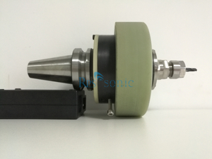
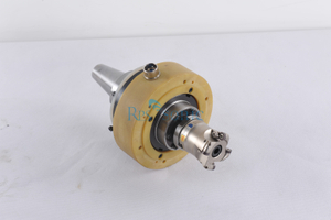
Ultrasonic Wire Drawing The Wire Drawing Process with Axial Ultrasonic Vibration consists of two systems of wire drawing and ultrasonic vibration. The wire drawing device consists of a rotating wire drawing drum (winch) and a die holder. The vibration system consists of an electric oscillation generator, a machine-electric transducer and a horn. The electric oscillation generator converts the 50 Hz AC power into a 6-60 kHz AC through a capacitor, an inductor, and a tube circuit. The machine-electric transducer converts the electrical oscillation into a magnetostrictive nickel or an electrostrictive ceramic. Mechanical vibration; the horn is a rod with a thick end and a thin end. The thick end is connected with the machine-electric transducer, and the vibration transmitted from the vibration source is received. The small end is used as the mold base, the fixed drawing die, the drawing force, and the vibration It is transmitted to the wire drawing die through the horn. In the case where the vibration frequency is fixed and the vibration energy is not lost, the effect of the horn is to increase the vibration amplitude when the cross-sectional area becomes small, and hence the name. There are two parameters of frequency and amplitude when vibration occurs. The particle has energy when it vibrates. When the mass of the particle is large, the frequency of the vibration is high, and the amplitude is large, the energy of the particle vibration is large. The propagation of vibration becomes a wave with two parameters of wavelength and amplitude. Vibration generally propagates in a traveling wave, but becomes a standing wave when subjected to a specific disturbance. The standing wave has two special positions: the node and the antinode. The amplitude of the particle at the antinode is the largest, and the amplitude of the node at the node is the smallest. When the ultrasonic frequency vibration propagates in the horn, the rod has ultrasonic waves whose wavelength can be calculated according to the vibration frequency and the elastic modulus of the rod material. The length of the rod should be such that a standing wave is generated within the rod. The mold as a vibrated particle point should be fixed at the antinode or at the node.
The direction of vibration to the wire drawing die can be axial, radial and tangential. Common axial vibration is applied. At this time, the wire drawing die should be placed at the antinode position of the standing wave, and the drawing direction is the same as the vibration direction. When radial vibration is applied, the wire drawing die should be placed on the node of the standing wave, and the outer circle of the mold faces the vibration source, that is, the wire drawing direction is perpendicular to the vibration direction.
Parameter:
| Model No. | UWD20 |
| Ultrasonic Frequency | 20Khz |
| Maximum Output | 100 Watt |
| Amplitude | 15um
|
| Power Supply | 220V / 50-60 Hz |
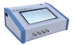
| Ultrasonic Generator | Size | 250(W) x 310(L) x 135(H) mm |
| Weight | 5 Kg |
| Feature | Ultrasonic Amplitude Adjustable |
ultrasonic energy can provide these distinct benefits:
Draw force can be reduced from 15% to 60%.
Draw speed may be increased from 20% to 200% or more depending on materials and conditions.
Surface finish can be improved.
It can eliminate stick-slip action (known as chatter).
Application of ultrasonic vibrations to most any metal forming process can offer these benefits to the process and finish.