
Ultrasonic weld joint design should be frozen only after the team has matched the thermoplastic material, joint style, energy path, horn contact surface, support tooling and weld-control method to the required weld outcome. The tooling shape comes later, because the horn, press and support tooling can only be selected sensibly when the part geometry and joint requirements are already clear.
Start with the weld outcome, not the tooling shape
Before committing to ultrasonic weld tooling, define what the joint must achieve, how visible it may be, how the plastic will transmit vibration and how the molded parts will be supported during welding.
- Define the weld requirement. Decide whether the joint is primarily structural, sealing, locating, cosmetic or a combination, because joint design for injection-moulded thermoplastics depends on weld requirements and aesthetics.
- Confirm the material family and geometry. Thermoplastic type and component geometry affect whether an ultrasonic weld is practical and which joint concept should be reviewed first.
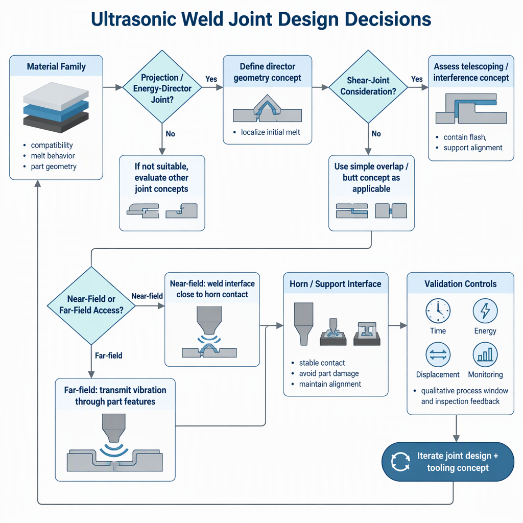
- Choose a preliminary joint approach. Projection or energy-director joints and shear joints are different design approaches, so the review should compare them against the part shape rather than treating them as interchangeable details.
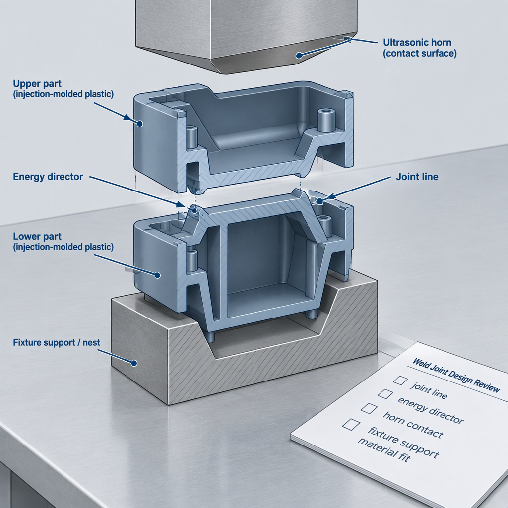
- Map the tooling interface. The welding stack, horn or sonotrode, press and support tooling all interact with the component, so the part needs surfaces that can be contacted, supported and controlled during the weld stroke.
- Plan validation variables. Time, energy and displacement modes are process choices to validate around the specific part, material and joint before production assumptions are locked.
For supplier-specific machine ratings, service scope, certifications or application testing, ask the supplier for current written documentation instead of assuming that general ultrasonic welding guidance proves a specific commercial capability.
Match the joint concept to the material family
Material selection is a joint-design decision because thermoplastic type, part geometry, weld requirements and appearance all influence whether a projection or energy-director joint, a shear joint or a different joining route deserves trial work.
| Question before tooling | Why it matters | Buyer action |
|---|---|---|
| Is the resin and grade known, including whether the material behavior supports ultrasonic energy transfer? | Thermoplastic type is one of the design factors for ultrasonic welding of injection-moulded components. | Collect resin data, molded-part samples and any additives or fillers information before joint trials. |
| Is the weld line expected to be hidden, cosmetic or load-bearing? | Weld requirements and aesthetics affect the joint design choice. | State strength, sealing, positioning and cosmetic acceptance criteria before fixture quotation. |
| Would an energy director concentrate vibration at the desired interface? | Projection or energy-director joint approaches are basic ultrasonic weld joint options for moulded thermoplastic components. | Review whether molded features can be added without sink, flash, stress concentration or assembly interference. |
| Would a shear joint better suit the application? | Shear joints are another basic joint approach and should be compared where geometry and weld requirements point away from a simple projection joint. | Check whether the part can tolerate the engagement length, alignment control and molded-wall support that a shear concept requires. |
Check the energy path from horn to joint line
A joint that looks practical in CAD may still be poor for ultrasonic welding if the horn cannot deliver vibration efficiently from its contact surface to the joint line.
| Energy-path question | Near-field review | Far-field review |
|---|---|---|
| Distance from horn contact to joint | Near-field welding considers the interface close to the sonotrode contact area. | Far-field welding considers a longer vibration path through the part before energy reaches the interface. |
| Material sensitivity | The material and part geometry still govern whether the joint feature can form a sound weld. | The longer energy path makes material behavior and geometry especially important to screen before tooling. |
| Evidence from composite work | Published thermoplastic-composite coupon work describes near-field ultrasonic welding and flat thermoplastic-film energy directors in a coupon-test context. | That coupon method supports energy-path thinking, but it should not be treated as a direct rule for every injection-moulded plastic part. |
Confirm horn contact, support and movement control
Horn, press and support tooling decisions depend on whether the molded component can be contacted, clamped, supported and moved repeatably during the weld cycle.
- Horn contact surface: identify a surface that can receive the sonotrode without damaging cosmetic areas or pushing the part out of alignment.
- Support tooling: confirm that the lower fixture can hold the part and resist weld forces without letting the joint open, rock or twist.
- Wall and joint support: check whether ribs, walls and molded features around the weld line can support the selected joint approach.
- Stress concentration: review sharp corners, thin sections and abrupt geometry changes near the weld because component design is part of weld planning.
- Assembly stack-up: confirm that part tolerances allow the joint features to meet before the press stroke or displacement limit is reached.
- Manual access safety: if engineers must place or remove samples around powered welding equipment during trials, switch off and disconnect the relevant power source before any manual access that the machine manual permits.
Define the weld-control question before validation trials
Do not choose a control mode as a slogan; choose the time, energy or displacement question that will be validated against the part’s weld requirement and inspection method.
| Control question | What it helps test | Pre-tooling implication |
|---|---|---|
| Should trials start with weld time control? | Time is one of the process modes discussed for ultrasonic welding parameters. | Useful for early screening, but the team still needs acceptance tests that show the weld outcome is repeatable. |
| Should energy input be controlled? | Energy mode is another process option for planning weld parameters. | Clarify how energy input will be interpreted when part fit, material variation or joint contact changes. |
| Should displacement or collapse be monitored? | Composite coupon methods describe displacement control and mechanical characterization by lap shear testing. | Translate any displacement target into a part-specific feature, weld collapse or inspection plan rather than copying a coupon value. |
| Should in-situ monitoring be part of validation? | A review of thermoplastic-composite ultrasonic welding discusses process windows, quality assurance and in-situ monitoring. | Decide which signals will be recorded during trials and which acceptance tests will confirm that the signal matters. |
For thermoplastic composites, the Frontiers review on ultrasonic welding of thermoplastic composites discusses energy-director heat concentration, control by time, energy and displacement, and the role of monitoring in process-window development.
Separate moulded-plastic guidance from composite evidence
Thermoplastic-composite research can inform energy-director and process-control thinking, but composite coupon evidence should not be copied directly into an injection-moulded plastic joint without part-specific trials.
| Evidence type | What it can support | What still needs application review |
|---|---|---|
| Injection-moulded thermoplastic component guidance | General questions about resin type, part geometry, weld requirements, aesthetics, joint concepts and near-field or far-field access. | Specific resin grades, molded tolerances, leak requirements, cosmetic limits and production inspection criteria. |
| Thermoplastic-composite coupon procedure | Near-field welding, flat film energy directors, process phases, displacement control and lap shear characterization in a coupon-test method. | How those coupon conditions translate to molded housings, clips, reservoirs, medical parts or consumer-product assemblies. |
| Thermoplastic-composite review | Principles such as energy-director heat concentration, interface temperature development and monitored process windows. | Part-specific acceptance limits, tooling details and inspection methods for a non-composite molded assembly. |
Use a pre-tooling checklist before freezing the design
A practical pre-tooling release should prove that the design team has answered material, joint, access, support and validation questions before horn or fixture geometry is finalized.
- Material family, exact grade, additives and molded-part condition are documented for trial planning.
- The selected joint concept is tied to the weld outcome, not only to available wall thickness.
- Energy-director or shear-joint features are reviewed for molding feasibility, flash risk, appearance and assembly fit.
- Near-field or far-field access is identified from the horn contact surface to the joint line.
- Horn contact, press stroke, fixture support and part movement are considered together rather than as separate purchasing items.
- Process parameters to be trialed include a planned approach to time, energy or displacement control.
- Monitoring or recorded process signals are connected to acceptance tests instead of being collected without a decision rule.
- If composite literature informs the review, its coupon or laminate scope is separated from injection-moulded part assumptions.
- Supplier discussions include requests for current product specifications, application-test scope, service terms and any certification documents relevant to the purchase.
Conclusion
The right next step is a disciplined design review: prove the material, joint concept, energy path, support tooling and control method before spending money on final ultrasonic weld tooling.
- Treat ultrasonic weld joint design as an application-selection decision, not a drawing detail.
- Review horn, press and support tooling interfaces while the molded-part design can still change.
- Use process monitoring and validation trials to connect control choices with actual weld acceptance.
FAQ: Ultrasonic weld joint design before tooling
These questions help process engineers, R&D teams and equipment integrators turn ultrasonic weld joint design into a pre-tooling decision checklist.
What is the first question in ultrasonic weld joint design?
Start with the required weld outcome: strength, sealing, positioning, appearance or another acceptance need. Joint geometry should then be selected around the thermoplastic material, part geometry and weld requirement.
Should the team choose an energy director before choosing a machine?
The team should first decide whether an energy-director or projection joint fits the material and molded geometry. Machine and horn choices are easier to discuss after the joint concept and access path are clear.
When is a shear joint worth considering?
A shear joint is worth reviewing when the part geometry, weld requirement and appearance need a joint concept beyond a simple projection feature. It still needs molded-wall support, alignment control and trial confirmation.
Why does near-field or far-field access matter?
Near-field and far-field access describe how vibration travels from the horn contact area to the joint interface. Longer or less direct paths make material behavior, geometry and support conditions more important to check early.
Can thermoplastic-composite welding studies be used for molded plastic parts?
They can inform questions about energy directors, near-field welding, displacement control and testing, but composite coupon studies are not automatic design rules for injection-moulded plastic assemblies.
Which control mode is best for ultrasonic welding?
There is no universal choice for every part. Time, energy and displacement control should be evaluated against the material, joint geometry, acceptance test and process-window evidence from trials.
What should be ready before asking for tooling design?
Prepare the part drawings, material information, weld outcome, preliminary joint concept, horn contact area, fixture-support assumptions and validation plan so the tooling discussion is tied to the real application.