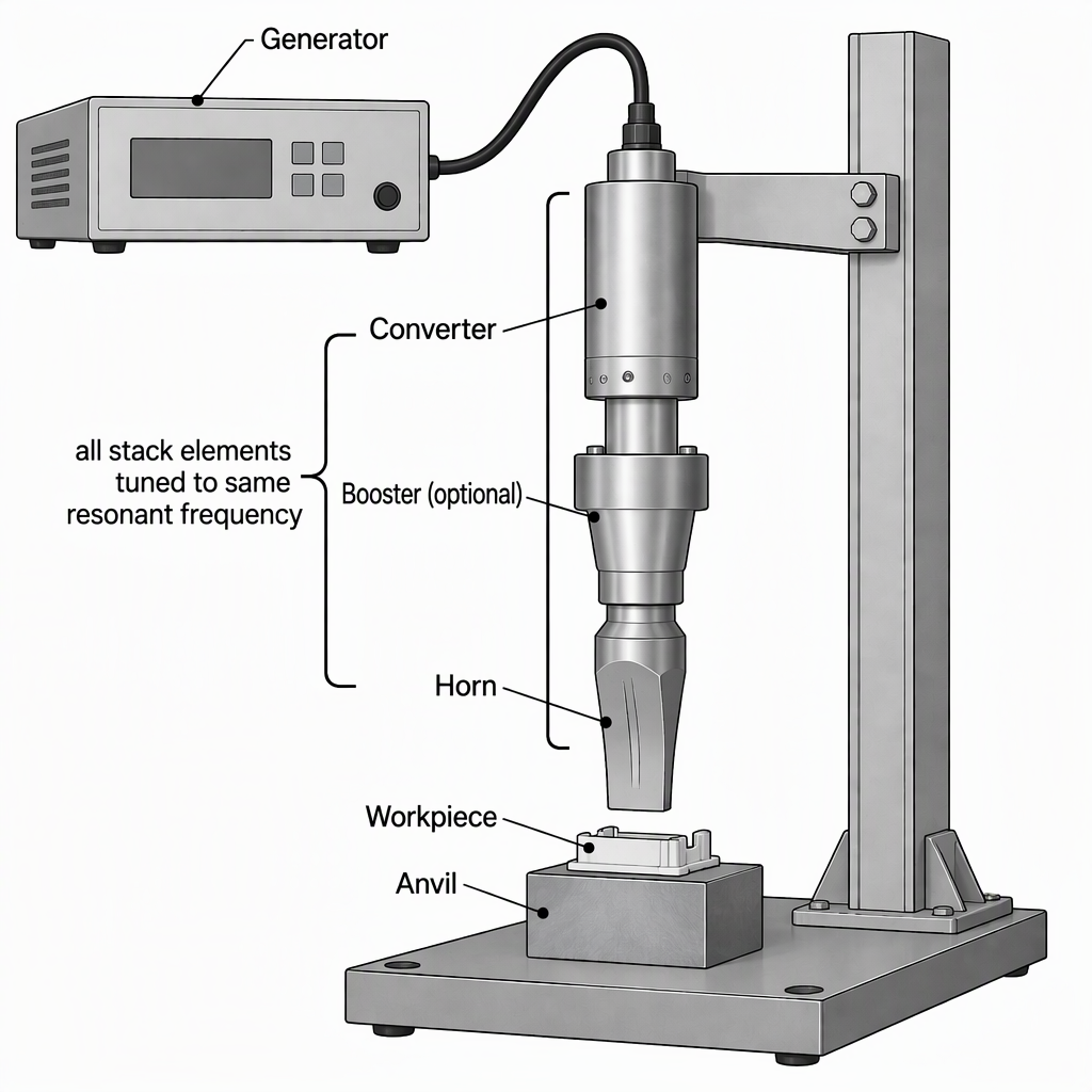
An ultrasonic stack is compatible when its generator, converter (transducer), optional booster and horn are all built for the same resonant frequency, and when their electrical and mechanical interfaces and their power or amplitude ratings correspond. Four components carrying the same frequency label are not automatically a working stack. Accept a combination only when you hold each element's frequency and rating, its interface drawing, and a written statement of what the combination was actually run against.
What Ultrasonic Stack Compatibility Actually Requires
Compatibility means the stack works as one resonant assembly driven at a single frequency: the converter, the booster (when one is used) and the horn are tuned to resonate at the same ultrasonic frequency, and the generator delivers a high-power electrical signal at that same resonance. Industrial ranges are commonly quoted at 15 kHz, 20 kHz, 30 kHz, 35 kHz, 40 kHz and 70 kHz.
A resonant match is the starting condition, not an acceptance test. The same stack principle serves two different joining mechanisms: metals are welded without melting the base metal, while thermoplastics absorb the energy and melt locally at the joint. A stack that resonates therefore tells you nothing yet about your joint design, the amplitude your part needs, or the weld you will actually get.
Keep frequency agreement as one line in the acceptance file, next to the interface drawings and the written statement of which combination was run together.
Matching the Generator to the Stack
The generator must deliver its high-power electrical signal at the stack's resonant frequency, and what it can output has to suit the converter and horn attached to it. Frequency agreement is the entry requirement; drive capability, and the way the generator finds and holds resonance, decide whether the combination behaves on your press.
A generator listed in the RPS-SONIC catalogue is described as having an intelligent frequency-control system that tracks a resonance point. Ask for that behaviour in writing, because it is the part of the match you cannot read from a nameplate.
- Rated operating frequency equals the converter's nominal frequency, stated on the datasheet rather than inferred from a label.
- Generator output is documented as adequate for the converter's rated power with your horn fitted.
- The generator's resonance-tracking or frequency-control behaviour is described in its manual.
- Cable, connector and machine interface — start signal, interlocks and mounting — match your press.
- The supplier states which converter and horn the generator is set up for or has been tested with.
- The output or amplitude setting range, and the setting used for your horn, are recorded.
Matching the Transducer (Converter) to the Generator
Start from the converter's own data: its nominal frequency and rated power must fall inside what the generator is designed to drive, its electrical connection must match, and the mechanical fit above and below it must be the one the stack was designed for. Then ask for evidence that this converter and this generator were run together.
- Isolate first. Switch the generator off and disconnect it from its power supply, then follow the machine manual's energy-isolation and access procedure. Never remove or fit a converter, booster or horn while the stack is connected to power.
- Record the converter's nominal frequency and rated power from its nameplate or datasheet.
- Compare those figures with the generator's rated operating frequency and output. If the generator's documentation does not cover the converter's rating, stop and ask before going further.
- Check the electrical interface: connector type, cable length and route, and whether the generator supplier lists this converter or an equivalent inside its limits.
- Check the mechanical interface: mounting flange, stud thread, spanner flats and overall length against the booster or horn above it and the press below it.
- Ask for the qualification record — a test sheet or written statement showing the converter and generator running together, with the frequency and power used.
- Fit the parts under the manual's procedure, restore power, and confirm the generator finds and holds its operating point before you run production parts.
Matching the Booster: Optional, Not Neutral
A booster is optional: a stack can be converter and horn only. When a booster is fitted it sits between the converter and the horn, must be tuned to the same resonant frequency as both, and adds length that the press stroke, mounting height and tooling clearance have to accommodate.
Stack without a booster
- Position in the stack
- The converter connects directly to the horn.
- Frequency requirement
- Converter and horn tuned to the same resonant frequency at which the generator drives.
- What changes on the machine
- Shortest assembly; horn mounting and press stroke are set for a converter-to-horn stack.
- Documents to request
- Converter and horn data, interface drawings, and the record of the two-element combination.
Stack with a booster
- Position in the stack
- The booster sits between the converter and the horn.
- Frequency requirement
- Converter, booster and horn all tuned to the same resonant frequency.
- What changes on the machine
- Longer assembly; press stroke, mounting height and tooling clearance must allow for the booster.
- Documents to request
- Booster frequency and interface drawing, plus a statement of what the three-element stack delivers at the workpiece.
Matching the Horn (Sonotrode) to the Rest of the Stack
The horn contacts the part, and it must be tuned to the same resonant frequency as the converter and booster while its mounting interface and geometry suit your joint. Horn design is application-specific, so the compatibility file needs a drawing and an amplitude rating for your horn, not only a frequency figure.
- Horn frequency is stated and matches the stack's resonant frequency.
- Stud thread, mating face and spanner flats match the booster or converter it attaches to.
- A horn drawing with dimensions and mass is supplied, so press stroke and clearance can be confirmed.
- The amplitude the horn delivers in this specific stack configuration is stated in writing.
- Where design analysis is offered, ask for it: an RPS-SONIC sonotrode listing describes the horn as FEA-analysed, so request the analysis summary and the assumptions behind it.
- Before fitting or removing the horn, switch the generator off and disconnect it from its power source, following the manual's isolation procedure.
One Resonant Frequency, Four Elements: The Compatibility Decision Table
Yes — the converter, booster and horn must all be tuned to the same resonant frequency, and the generator must drive at that frequency. Matching nominal figures is necessary but not sufficient: the electrical and mechanical interfaces and the power and amplitude demand of your horn must correspond as well.
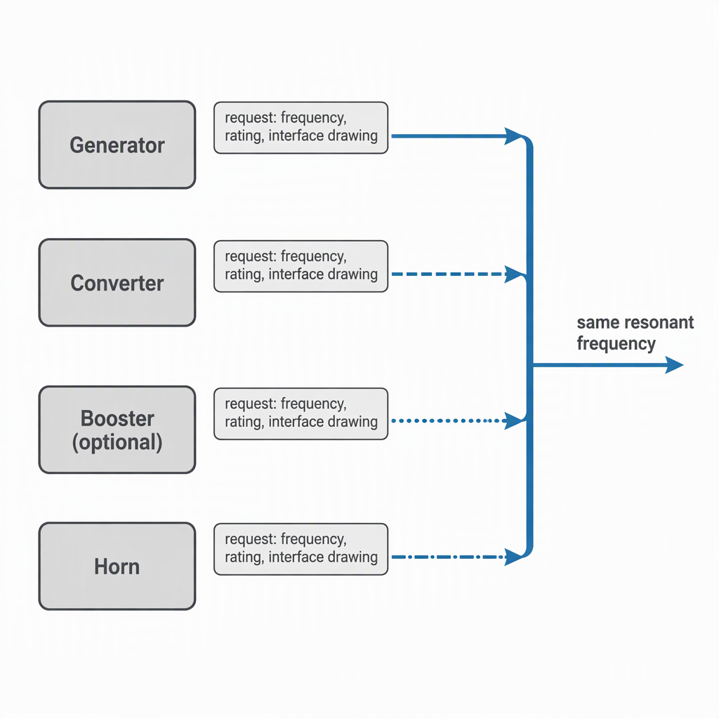
What must correspond across a four-element stack | Element | Function in the stack | What must correspond | Evidence to request before acceptance |
| Generator | Supplies the high-power electrical signal at the stack's resonant frequency. | Operating frequency equals the stack resonance; output suits the converter and horn fitted. | Datasheet with frequency and output rating, a description of its frequency control, and the converter and horn it is set up for. |
| Converter (transducer) | Converts the electrical drive into mechanical vibration at the tuned frequency. | Nominal frequency same as generator and horn; rated power consistent with the generator; connector and mounting interface identical to the drawing. | Datasheet, interface drawing, and a test record showing it running with this generator. |
| Booster (when fitted) | Sits between converter and horn and is tuned to the same resonant frequency. | Frequency, overall length for the press stroke, and both mating interfaces. | Booster drawing, stated frequency, and what the complete stack delivers at the workpiece with it in place. |
| Horn (sonotrode) | Transfers the vibration into the joint area. | Frequency, interface to the booster or converter, amplitude demand against stack capability, and geometry for your joint. | Horn drawing, frequency and amplitude rating, and a design-analysis summary where one is offered. |
Send the machine and the stack you already have, not just a frequency: machine make and model, generator nameplate data, the existing converter, booster and horn with part numbers and dimensions, and drawings or photographs of every interface. RPS-SONIC states that it asks for full machine information before supplying a component so that the part does not create a connection and matching problem. Treat that exchange as the start of the check, and still ask for the documentation that results from it.
- Machine: make, model and press type, with a drawing or photographs of the mounting interface.
- Generator: make, model, rated frequency, output rating, a nameplate photograph and the connector type.
- Existing stack: part numbers and labels for converter, booster and horn, with frequency, power or amplitude figures, dimensions and mass.
- Interfaces: close-up photographs of studs, mating faces, spanner flats, and the cable and connector.
- Application: part material and grade, joint design, weld area, part drawing, and the production rate you need to reach.
- What you expect back: per-element frequency and rating, interface drawings, a statement of which combination was run together, and the acceptance checks you can repeat on your own machine.
Where Stack Matching Stops: Noise, Safety and Weld Quality
Matching fixes the resonant frequency and the interfaces; it does not by itself establish weld quality, a safe noise exposure limit, or the right amplitude for your part. Those are separate questions answered by your own weld trials, by your EHS function, and by the limits the element manufacturers document.
Process first. Metals and thermoplastics are joined by different mechanisms under the same stack principle, so a compatible stack is only the delivery system for a joint design you still have to prove on samples.
Noise second. High-frequency sound can damage hearing, and enclosing the machine or using ear protection are the mitigations usually cited. Because the hazard includes airborne ultrasound, an ordinary audible noise reading does not settle the question: the US National Institute for Occupational Safety and Health recommends an exposure limit of 85 dBA as an 8-hour time-weighted average with a 3 dBA exchange rate, but that figure is a benchmark for audible occupational noise, not a limit for ultrasound. Ask your EHS function for a measurement and control plan covering the frequencies your machine produces.
Third, power safety. Any inspection, cleaning or component change on the stack starts with switching the generator off and disconnecting it from its power source, then following the manual's permitted access procedure.
Conclusion
Build the acceptance file before you accept the stack: one line per element with its frequency and rating, an interface drawing for each joint in the stack, and a written statement of which combination was run together. Then isolate the power before any fitting, re-check the operating point on your machine, and prove the joint on samples before production.
Frequently Asked Questions
These are the questions engineers ask most often when a supplier proposes a generator, converter, booster and horn as one matched stack.
Can I pair a generator from one brand with a transducer from another brand?
Sometimes such a pair runs, but the brand label is not the evidence. What matters is whether the converter's frequency and power rating fall inside what the generator is designed to drive, whether the connector and mechanical interface match, and whether the specific pair has been documented running together. Catalogues that group transducers by brand family, with figures such as 15 kHz 2600 W or 20 kHz 2000 W, describe what is offered for each item; they do not show that any cross-brand pair is qualified.
Which ultrasonic frequency should I choose for my stack?
There is no universally best frequency. Industrial ranges are commonly quoted at 15 kHz, 20 kHz, 30 kHz, 35 kHz, 40 kHz and 70 kHz, and the stack must be built around whichever one you choose. Decide it with your horn and converter supplier using your part and joint data, then require the generator, converter, booster and horn all to be specified at that single frequency.
The hardware principle is shared, but the joining mechanism differs. In metals the weld is made without melting the base metal; in thermoplastics the material absorbs the energy and melting is local at the joint. That difference changes the tooling, the joint design and the amplitude you need, so ask for experience in your own material class.
Do operators need hearing protection around an ultrasonic welding stack?
High-frequency sound can damage hearing, and enclosing the machine or using ear protection are the mitigations usually cited. Because the hazard includes airborne ultrasound, an A-weighted audible reading alone does not answer the question. Ask your EHS function to measure the frequencies your machine produces and to set the controls, rather than copying a limit from a noise poster.
Can a booster be used to raise amplitude to any level I need?
A booster is optional, and once fitted it becomes part of the resonant stack, so it must be tuned to the same frequency and its interfaces must fit the converter above and the horn below. Ask what the complete stack delivers at the workpiece with and without the booster, and stay within what the converter and horn are documented to take. If you need more than that, the horn or converter changes too.
If all parts are rated at the same frequency, is the stack compatible?
No. The same nominal frequency is a necessary condition, not the test. The interfaces must mate, the generator must be able to drive that converter and horn, the amplitude demand must sit inside the stack's documented limits, and someone must be able to show the exact combination running together.