I. Overview
PPS (polyphenylene sulfide) is a semi-crystalline thermoplastic with a steep melting curve and a high melting temperature (285 ° C, 545 ° F), and its pure PPS is not suitable for ultrasonic welding. However, after the addition of glass fiber and other fillers, the rigidity of the PPS mixture is greatly increased, which contributes to ultrasonic vibration transmission, so ultrasonic welding can be used. Under the condition that the welding ribs are designed reasonably, the glass fiber content of 40% PPS can be easily welded. However, when the glass fiber content and the mineral powder are continuously increased, the ultrasonic component is difficult to be formed because the content of the resin component in the mixture becomes low.
2. Welding rib design
The welding rib design of the PPS product is critical to the weld strength. The design of parts and weld ribs needs to be considered from the assembly of the components, as well as the impact of these designs on the ultrasonic welding process.
For the welding of PPS materials, the shear seam design is generally adopted. For the design of triangular or energy-saving ribs, different types of PPS with different compositions have different welding results. For PPS mixtures with high filler content, there is not enough fluidity when melting, and it is impossible to flow into both sides to form more bonding areas. Therefore, such PPS mixtures are not suitable for the design of triangular or energy-saving ribs.
For shear joints, a similar "smear" action is produced at the joint interface during the welding process, resulting in greater fluidity of the molten plastic and easier soldering. Tests have shown that for PPS with a high filler content, the product using the shear joint has a pull-out force that is six times that of the stepped weld. At the same time, the shear seam melts and bonds to a larger area, which helps seal.
Typical shear and step welds are shown in Figures 1 and 2 below.


For products with a maximum size greater than 89 mm or an irregular shape, it is difficult to control the injection molding error, resulting in unstable welding results. Therefore, the shear seam design is not recommended for products with large or irregular shapes, but the triangular conductor/step/groove design is recommended. In general, the weld depth of the shear joint is approximately 1.25 times the wall thickness.
For ultrasonic near-field welding of PPS thin-walled parts, high-frequency (eg 20Khz or 30Khz) and low-amplitude welding processes are more likely to be successful. At the same time, it has the advantage of low instantaneous power and protection against damage to components. When using the energy guiding rib design, for a typical semi-crystalline material, the triangular rib angle is 60°, the bottom width is generally 20%-25%, and the height is 0.866 times the width of the bottom.
It is important to keep in mind when designing products that choose an ultrasonic welding process that must minimize unnecessary ultrasonic energy losses. The ultrasonic waves propagate in the direction of the movement of the welding horn and the energy is proportional to the wall section size. The part to be vibrated should be the uppermost and lightest part of the assembly, and a larger flat surface that is in contact with the welding horn should be designed above the welding bead. Sometimes it is necessary to design a special structure to transfer vibrational energy directly to the weld, for example by adding a raised lip structure at the edge of the lid. Proper part assembly clearance is also necessary to avoid interference and lead to solder joints. The parts on the vibration path should be rounded and the fillet size is 0.6 times the wall thickness to avoid cracking of the parts during ultrasonic welding. Symmetrically designed parts are easier to weld because of their uniform pressure and energy distribution.
In summary, the following are the wrong weld designs to avoid:
1. The gap design of the assembly component is too small, and there is a tight or interference fit, which prevents the ultrasonic vibration from being effectively transmitted to the welding rib;
2. The cross section of the part transmitting the ultrasonic vibration is too small/thin, resulting in cracking at a large amplitude;
3. If the size of the weld bead is too large, the instantaneous power output will be too large, which may damage the parts;
4. The part that is in direct contact with the welding horn is not the most advanced and lightest part in the assembly;
5. Internal sharp corners may cause parts to crack;
6. The internal metal insert absorbs ultrasonic vibrations and reduces welding efficiency, so metal parts should be assembled after ultrasonic welding.
3. welding process recommendations
The optimum ultrasonic welding process is highly dependent on part quality and assembly accuracy, as well as the welding equipment and fixtures used. It is important to seek the advice of the manufacturer during the product design phase. The adjustment of the welding parameters should take into account the material composition, dimensional error and stiffness of the part, as well as the distance between the position of the welding horn and the product and the weld. The weldability of the product refers to the ability of the material to transmit ultrasonic vibrations without damage.
Since PPS is a high melting point semi-crystalline thermoplastic, large amplitude ultrasonic vibration is usually required to melt the plastic to form a weld. Considering the high modulus (high stiffness) properties of the PPS, the amplitude of the output can be transmitted over a considerable distance in the plastic part. The greater the distance between the horn and the weld, the greater the amplitude required. In the near field welding (the distance between the welding horn contact surface and the weld is less than 6mm), higher welding efficiency can be achieved by using a high frequency and lower amplitude welding process. In far field welding (the distance between the welding horn contact surface and the weld is greater than 6 mm), the amplitude transmission distance is limited by the product structure. When the wall is thinner, the ultrasonic vibration transmission distance is shorter.
The power required for welding depends on the size of the weld area, the geometry of the part and the absorption characteristics of the material. PPS welding usually requires high power output to ensure that most of the energy is transferred very quickly to the weld while avoiding vibration damage to the part. The speed of the weld horn is matched to the melting of the PPS plastic and the forming speed of the weld.
When the product is designed with a shear seam, the initial parameters can be set to high power output, large ratio ratio modulator, low welding pressure, and slower welding speed. Then, according to the actual welding results, the next adjustment is made. When soldering, be aware that large amplitude and long-term vibration can damage the surface of the part. The maximum weld strength is formed during the holding phase. If the airtightness is not good, the dynamic pressure holding distance or the holding time can be increased to improve.
When using the shear seam design, it is necessary to pay attention to the side support of the product wall to avoid the problem of poor welding strength due to the opening of the side wall of the part during welding. The fixture can be made of aluminum, steel, resin or other materials. The fit between the fixture and the product should be appropriate to provide proper support and facilitate the handling of the parts.
4. welding strength
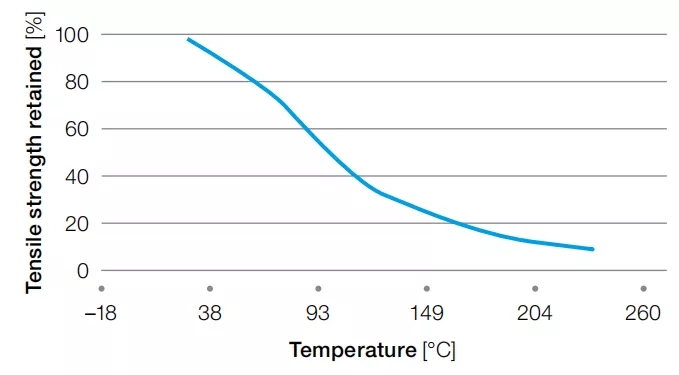
The strength of the weld is usually much lower than the bulk material. Because there is almost no glass fiber on the weld, the weld strength is mainly determined by the strength of the resin itself. That is, when welding pure resin materials (excluding glass fiber reinforced), the weld strength is usually not as large as the bulk material. For certain PPS materials, the weld strength can reach 50Mpa; for most PPS materials, the weld strength is less than 35Mpa. In addition, the weld strength decreases with increasing temperature, as shown in the following figure (pure tensile strength of pure PPS as a function of temperature).
In addition, there are many other factors that affect the weld strength:
Area of the welding area. The longer the wire, the more molten plastic, the greater the weld strength. But in fact, affected by factors such as injection molding accuracy and fixtures, the area of the welded area will be much smaller than the design expects.
·
Injection molded parts dimensional accuracy and quality. Injection defects such as voids absorb ultrasonic vibrations and affect energy transfer. May cause burns and internal cracks on the surface of the part, as well as lower weld strength.
·
Such surface contamination of the lubricant or mold release agent reduces frictional heat generation and hinders the welding process. At the same time, the weld strength is impaired due to impurities entering the weld.
During the welding process, the PPS plastic at the weld is rapidly melted and rapidly cooled, and it is easy to produce more amorphous (amorphous) state. When the product is used at temperatures above 85 ° C, the PPS will gradually transform into a semi-crystalline state, creating additional stress inside the product.