How to make perfect ultrasonic horn& transducer matching
1. Ultrasonic transducer principle and design (ultrasonic vibration system) matching
Abstract: The design and calculation of the ultrasonic transducer system of plastic welding machine, and the use of PRO-E three-dimensional software to draw a three-dimensional model, followed by frequency analysis, provides a useful design method for the ultrasonic transducer system.
Keywords: ultrasonic transducer, ultrasonic vibrator, ultrasonic vibrator, ultrasonic vibration system
In contemporary society, various products of plastics have penetrated into various fields of daily life. The traditional processing technology can no longer meet the development needs of the modern plastics industry. Ultrasonic plastic welding machine does not need to add any adhesive, filler or solvent, and does not consume a large amount of heat source when welding plastic products. It has the advantages of simple operation, fast welding speed, high welding strength and high production efficiency. Therefore, ultrasonic welding technology is becoming more and more widely used. Ultrasonic transducing systems usually include ultrasonic transducers and ultrasonic horns, which are the basic components for ultrasonic welding, and good ultrasonic transducers are prerequisites for ultrasonic welding.
2.1 Ultrasonic transducer design
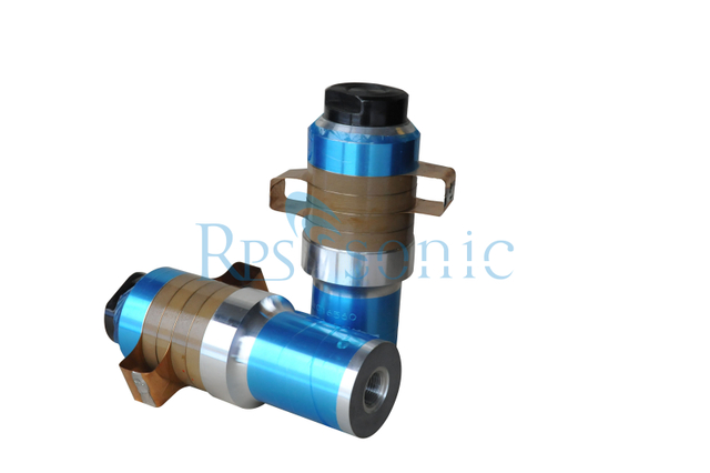
When the ultrasonic plastic welding machine is working, the processing of the plastic workpiece requires high-frequency longitudinal vibration, so that the upper and lower molds of the workpiece vibrate and melt the upper and lower layers to obtain the welding effect. Therefore, the type of transducer is selected as a longitudinal composite transducer, and the structure is simple, and the schematic diagram is shown in FIG. 2 . The first and last two pieces are metal cover plates; the middle is a piezoelectric ceramic crystal pile, which is generally a longitudinally polarized round hole or round tube, or a radially polarized round tube; a stress screw tightens the three parts Tightly pressed.


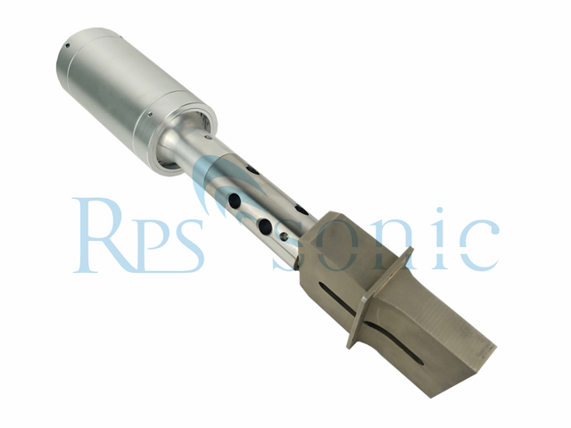
Ultrasonic horn
Ultrasonic horn structure diagram
Ultrasonic welding head
Stepped ultrasonic mold
Using PRO-E software to analyze the frequency of the horn, firstly, the 3D model of the horn is drawn by PRO-E 3D software according to the size of the horn. Secondly, the frequency analysis tool is used to analyze the frequency of the horn. The input low frequency value is 20000 Hz, the material is 2A01 and the elastic modulus of the material is 0.7×10⁵ MPa, which is 0.3. After the analysis results are shown in Figure 4, the vibration frequency at the output of the horn is 20544 Hz, which is not much different from the initial frequency value of 20 kHz, so it can meet the design requirements.
2.3 Ultrasonic welding head design
When the ultrasonic plastic welding machine is working, the force exerted on the workpiece by the tool head is about 30 to 50 N, so the force is not large, and it is a medium-strength working condition, so that the hard aluminum of the model 2A01 can be selected as the manufacturing material. . For the tool head to work properly, the part of the tool head that is connected to the output of the horn is matched. Matching refers to impedance matching between the output of the horn and the input of the tool head. It is therefore required that at the resonant frequency on their joint faces, the output impedance of the horn is equal to the input impedance of the tool head. According to the knowledge mentioned above, the equal impedance of the two only requires their cross-sectional areas to be equal.
Ultrasonic welding head drawing
Using PRO-E software to analyze the frequency of the ultrasonic welding head, firstly, the 3D model of the tool head is drawn by PRO-E 3D software according to the size of the welding head. Next, the tool head was analyzed for frequency. The input low frequency value was 20 kHz, the material was 2A01, and the material's elastic modulus was 0.7×10⁵ MPa, 0.3. Frequency analysis chart

Ultrasonic welding head inspection
It can be seen that the small end face part of the welding head head is also the resonance frequency of the upper part of the figure is 20021 Hz, which is not much different from the frequency of the first given ultrasonic wave of 20 kHz. Therefore, the design of the tool head can meet the design requirements, and the working time can be The vibration transmitted by the transducer through the horn to the input end of the horn head resonates.
Ultrasonic welding head frequency analysis
According to the vibration equation of any variable cross section, the general solution of the vibration equation is solved under the condition that the coordinates and boundary conditions of each part of the vibrator are known, and then the frequency equation and the vibration velocity are obtained around the boundary conditions of the general solution and the ultrasonic transducer. Ultrasonic transducers were designed with a series of knowledge of the stress distribution equation and the characteristics of the piezoelectric effect ceramic material. According to the working condition of the ultrasonic plastic welding machine, the type of horn is selected; according to the amplitude amplification factor, the relationship between the power of the wave and the amplitude, the cross-sectional area of the horn is obtained; the general solution according to the vibration velocity equation and the horn Convenient conditions, calculate the stress and vibration velocity distribution of each part of the horn. According to the frequency equation and the strength condition, the welding head of the ultrasonic plastic welding machine was designed.
Ultrasonic transducer parameter test
Through a series of knowledge design and calculation, the dimensions of the ultrasonic transducer, horn and tool head are determined, and the spectrum analysis is carried out by PRO-E software to verify that it meets the design requirements. Thus, the vibration system design of the ultrasonic plastic welding machine is completed, which provides useful design steps and methods for the ultrasonic vibration system.
2. Selection of ultrasonic transducers:
An ultrasonic transducer is an energy conversion device whose function is to convert the input electrical power into mechanical power (ie, ultrasonic waves) and then pass it out, while it consumes a small amount of power (less than 10%). Therefore, the problem to be considered when using an ultrasonic transducer is the matching with the input and output terminals, followed by the mechanical mounting and mating dimensions. There are many types of ultrasonic machinery on the market, and customers must provide accurate and reliable indicators to ensure that the ultrasonic transducer products provided by the company can be well matched with your company's ultrasonic machines to achieve good performance.
Ultrasonic transducer
Ultrasonic transducers and ultrasonic vibrators should pay attention to the following parameters:
1 Resonant frequency: f, Unit: KHz
The frequency refers to a frequency measured by a transmission line method using a frequency generator, a millivoltmeter, or the like, or a frequency measured by an impedance analyzer or the like. Generally known as the small signal frequency. Opposite to it is the upper frequency, which is the actual operating frequency measured by the customer when the transducer is connected to the drive power supply via a cable and is unloaded or loaded. Because the matching circuits of the customers are different, the same transducers are different in frequency with different driving power sources. Such frequencies cannot be used as order basis.
2 Transducer capacitance: CT, unit: PF
That is, the free capacitance of the transducer can be measured by a capacitor bridge at a frequency of 400 Hz to 1000 Hz, and an impedance characteristic analyzer can also be used. To be simple, the measurement with a general portable capacitance meter can also meet the requirements.
3 transducer working mode
Due to different processing methods and requirements, the working mode of the transducer can be roughly divided into continuous work (lace machine, CD set machine, zipper machine, metal welding, etc.) and pulse type work (such as plastic welding machine). Different working methods The requirements for the transducer are different. In general, continuous operation has almost no pause time, but the operating current is not very large, the pulse operation is intermittent, there is a pause, but the instantaneous current is very large. On average, the power of both states is large.
4 transducer type and high power
The machine manufacturer may have different specifications for the nominal power of the machine for different purposes and purposes. In other words, the same transducer may have different nominal powers used on different machines. In order to avoid ambiguity, the customer should specify the structure of the transducer, such as column type, inverted horn type, etc., and the diameter and number of piezoelectric ceramic wafers.
5 Installation and mating dimensions
There are mainly ultrasonic horn materials, surface treatment methods and shapes. The ultrasonic transducer is connected with the ultrasonic horn, the ultrasonic horn is connected with the ultrasonic mold, and the diameter, thickness, notch or screw hole number and position of the ultrasonic horn flange.