- All
- Product Name
- Product Keyword
- Product Model
- Product Summary
- Product Description
- Multi Field Search
 English
Views: 29 Author: Site Editor Publish Time: 2019-07-24 Origin: Site
Ultrasonic probe ultrasonic flaw detection principle and sensor test and design
Ultrasonic transducers, horn and vocal sleeves are devices that convert electrical energy into vibration. To understand the principle of operation, a comparison can be made between an ultrasonic welder and a car.
The sensor performs energy conversion (as a motor), the transformer adjusts the ratio between force and speed (such as a gearbox), and finally the ultrasonic/ultrasonic horn directs and applies that energy to perform the required work (as a wheel).
In automobiles, all mechanical system components must be designed with harmonics to maximize energy transfer efficiency. The same is true for ultrasound systems, however, in this case, the key parameter of efficiency is the frequency of the component that should be as close as possible (eg 20 kHz +/- 50 Hz).
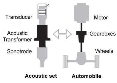
(An analogy between acoustic ultrasonic welding and the mechanical system of a car.)
Operating
The sensor has two operating frequencies that can be easily identified in its electrical impedance curve. The impedance maximum corresponds to the anti-resonant frequency (maximum speed). The ultrasonic welding system operates at an anti-resonant frequency. The impedance minimum corresponds to the resonant frequency (maximum force). The ultrasonic cleaning system operates at a resonant frequency.
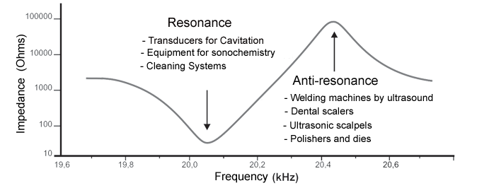
(The impedance curve of the sensor versus frequency.)
Increase the ultrasonic / horn frequency:
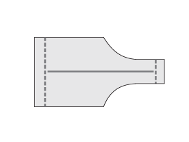
(Reduce the length of the ultrasonic electrode/horn to increase the frequency.)
Reduce the ultrasonic /horn frequency:
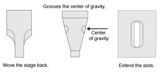
(The step of reducing the ultrasonic/horn frequency.)
Sensor test
To function properly, the frequency and impedance of the sensor must be within tolerance. For example, for a welding system, the frequency should be 2.5% higher than the nominal acoustic setting frequency with a tolerance of +/- 0.25%.
The decisive factors of frequency and impedance are the dimensional accuracy of the part, the tightness of the application, the quality of the ceramic and the tuning (similar to the case of ultrasonic propagation).
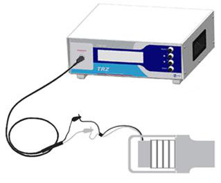
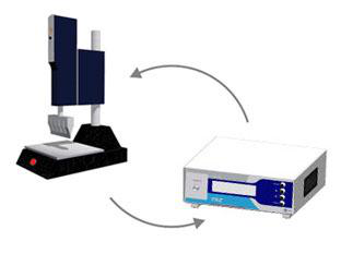
(The frequency and impedance of the transducer are determined using a TRZ analyzer.)
Acoustic test
The frequency and impedance of the acoustic group must be within an acceptable range. In a welding system, the frequency tolerance is ±0.25%, for example 20khz ± 50Hz.
Performance depends on frequency tuning and consistency between components. This can happen when combining sensors and converters (one low frequency and the other high frequency) even when operating at the correct frequency. This type of problem is detected by measuring the impedance.
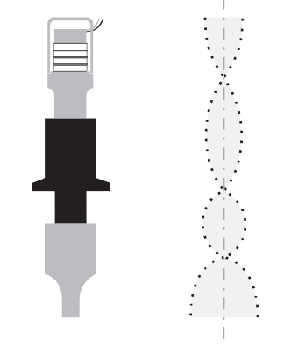
(Ultrasonic welding acoustic vibration amplitude.)
Piezoelectric ceramic test
Piezoelectric ceramics are the sensor core and key components. For power applications, PZT-8 and PZT-4 are commonly used.
The microcracks of the ceramic must be demonstrated before reassembly. With the TRZ software, cracks can be easily detected by abnormal peaks in the impedance curve.

(Testing Piezoelectric Ceramics with TRZ Software)
Predictive maintenance
With predictive maintenance, problems in the ultrasound system can be easily avoided. In general, the frequency deviation represents wear and the coupling problem is represented in the impedance. These problems are solved by retightening and polishing the interface.
(Predictive maintenance of systems using TRZ for cutting and welding)