- All
- Product Name
- Product Keyword
- Product Model
- Product Summary
- Product Description
- Multi Field Search
 English
Views: 166 Author: Site Editor Publish Time: 2019-06-17 Origin: Site
How to design a perfect ultrasonic cutting knife
The structural design of ultrasonic cutter for cakes
Abstract: An ultrasonic cutter of 20 kHz for food is designed to meet the demand of cutting large viscoelastic food. By analyzing its model with the finite element method, the natural frequencies of all orders and the distribution of displacement amplitude of cutter edge are obtained. The influence of the structure size on the uniformity of displacement at the output port, the longitudinal natural frequency of vibration and the adjacent frequency are analyzed. The structural parameters with high sensitivities are redesigned to make the cutter dominated by the longitudinal vibration near 20 kHz. The interval between the resonant frequency and the natural frequencies is large enough, and the distribution of displacement amplitude on the cutting edge surface is greatly improved.
In the cake industry, ultrasonic-assisted cutting are widely used because they do not require sharp edges and large pressure, and the material to be cut is not easily caused by tearing, breakage, deformation, and sticking
we have studied the auxiliary processing technology of high performance alloys, composite materials and brittle materials. we studied ultrasonic cutting knives, designed a cutting knives and established a dynamic model and structural optimization program. Our technical performed combined vibration processing on the workpiece of sintered NdFeB material by ultrasonic rotary processing method, which prolonged the service life of the tool. However, most of the processing objects of ultrasonic vibration aids are engineering materials, and few study on ultrasonic vibration aids for soft materials such as cakes.
The basic components of the ultrasonic cutting device are an ultrasonic generator, a transducer, a horn, and a cutting blade (tool head). When cutting the material, the cutter applies the mechanical energy transmitted by the horn to the material being processed to obtain a high-quality cutting effect . Traditional design theory starts with the classical theory to calculate the structural size . In actual production, due to the relatively large volume of the cutting object, a cutting blade of suitable thickness and width is required, and the calculation is complicated. In this paper, the finite element software ANSYS is used to design a cutting tool with pure vibration mode, uniform amplitude distribution of cutting edge and accurate resonance frequency.
1 cutting knife basic structure design
This article uses a 250 mm cylindrical cake as the cutting object. The design target frequency (FREQ1) is 20 kHz, longitudinal vibration mode.
The cutting blade size is W = 260 mm, H1 = 30 mm, H 2 = 5 mm, L1 = 50 mm, L2 = 69 mm, L3 = 50 mm. As shown in Figure 1, the material is made of food grade stainless steel 316L.
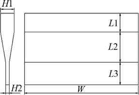
Fig.1 Schematic of ultrasonic cutter
1.1 vibration identification
The shape of the cake cutter is similar to that of a flat plate. This type of structure has a dense frequency characteristic. Through the finite element software, many scholars have analyzed the multi-dimensional coupled vibration form of similar structures and completed the structural optimization [8-10]. In this paper, the modal analysis of the cutting blade shows that there are many modes in the cutting blade, and different modes correspond to different modes and different natural frequencies. When the structural dimensions of the cutter change, the modal order and mode shape may change, which is not conducive to ANSYS analysis. Therefore, the optimization design of the cutting blade first needs to identify the various modes and extract the corresponding natural frequencies.
1.2 Determination of the number of slots
In order to reduce the lateral vibration, improve the uniformity of the amplitude and displacement distribution of the cutting edge, and avoid the interference of the adjacent vibration mode, it is realized by opening some slots on the cutting blade and changing the structure of the large end. The number of slots can be accurately determined using the optimized design module of ANSYS finite element software. First, parameterize the cutter model. The solid186 solid element is selected, and the cells are divided by the free meshing method. When the cutter structure changes, the unit can be freely extended. The Solid186 unit is a 20-node elastoplastic solid element with plasticity, creep, stress stiffness, large deformation and large strain capability. Attributes of 316L: Density r =9800 kg/ m3, modulus of elasticity E =201 GPa, Poisson's ratio m =0.3.
(1) Optimize variable settings
The objective function of the cutter mathematical model is SUB_UX, and the state variables are MFREQ1, MFREQ2, and MFREQ3. The specific meaning is defined as follows:
Uniformity SUB_UX: output longitudinal displacement minimum / maximum;
Frequency interval MFREQ1: resonant frequency of longitudinal vibration
The absolute value of the 20 kHz difference;
Frequency interval MFREQ2: the absolute value of the difference between the resonant frequency of the longitudinal vibration and the next-order frequency of the longitudinal vibration;
Frequency interval MFREQ3: Absolute value of the difference between the resonant frequency of the longitudinal vibration and the upper frequency of the longitudinal vibration
Design variables into the number of slots, then select optimization tools and optimization methods, specify optimal loop control methods, and optimize
Analysis.
(2) Analysis of results
After the solution is completed, the influence of the number of slots on the natural frequency of the vibration mode of the longitudinal vibration is shown in Fig. 2. The influence on the frequency interval is shown in Fig. 3 and Fig. 4, and the influence on the uniformity of the output terminal is shown in Fig. 5.
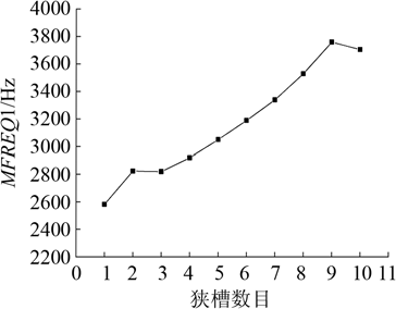
Fig.2 Influence of the number of narrow slots on longitudinal vibration frequency(MFREQ1)
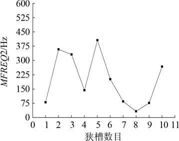
Fig.3 Influence of the number of narrow slots on frequency spacing (MFREQ2)
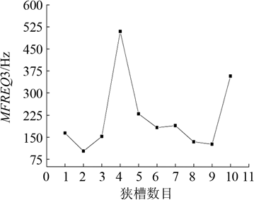
Fig.4 Influence of the number of narrow slots on frequency spacing (MFREQ3)
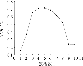
Fig.5 Influence of the number of narrow slots on uniformity(SUB_UX)
From the above results, when the cutter has 4 or 5 slots, it has a high uniformity and is an optimum value. Its effect on the frequency interval is similar. Since the result is simpler in 4 slots and MFREQ1 is smaller, 4 is selected as the number of slots. At this time, since the grooving changes the structure of the cutter, and MFREQ2 and MFREQ3 are less than 500 Hz, the longitudinal vibration mode is susceptible to the nearby modal interference; the resonance frequency that generates the longitudinal vibration is also far from the target frequency. Therefore, on the basis of determining the number of slots, by changing the distance between the slots, the size of the structure, the angle of rotation and the shape of the input end of the cutter, the structure of the cutter is further optimized to meet the requirements of the production. Port uniformity, frequency spacing, and proximity to target frequency.
2 sensitivity analysis of cutting blade structure
The shape of the cutter after slotting and changing the large end structure is complicated, and the change of the size of each structure affects the vibration characteristics of the cutter. In the secondary optimization, in order to obtain the optimal solution of the cutting blade, a structure with high sensitivity to the vibration characteristics can be selected as the design variable. Through the sensitivity analysis of the size of the cutting blade, the degree of influence of the structural change on the vibration characteristics such as the natural frequency, frequency spacing and uniformity of the cutting blade can be obtained. Provides the basis for selecting design variables to optimize the design. After machining and heat treatment, the vibration characteristics of the cutting tool have inevitable errors. Therefore, the analysis results can also provide a basis for the correction of the cutting blade. The structure selected for the sensitivity analysis of the cutting blade is shown in Figure 6.
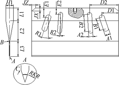
Fig.6 The structure for sensitivity analysis
Analyze the structure of the cutter by sensitivity analysis
Sensitivity of SUB_UX, FREQ1, MFREQ2, MFREQ3
the results are shown in Figures 7~10.
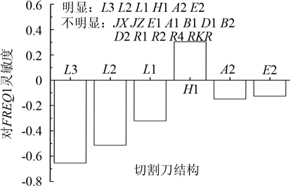
Fig.7 Influence of the structure of cutter on longitudinal vibration frequency(FREQ1)
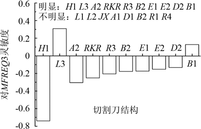
Fig.8 Influence of the structure of cutter on frequency spacing between longitudinal vibration frequency and previous order vibration frequency(MFREQ3)
The structure of the cutter has a relatively large influence on the longitudinal vibration resonance frequency, which is L3, L2, L1, H1, A2, and E2. Among them, as the size of L3, L2, L1, A2, E2 increases, the longitudinal vibration resonance frequency decreases; as the H1 size increases, the longitudinal vibration resonance frequency increases, as shown in Figure 7.
In the structure of the cutter, the influence of the longitudinal vibration resonance frequency and the frequency interval of the previous-order mode is relatively large, which are H1, L3, A2, RKR, R3, B2, E1, E2, D2, and B1. Among them, H1, A2, RKR, R3, B2, E1, E2, D2 increase with the above size, the frequency interval decreases, L3, B1 increase with the increase of the above size, the interval increases, as shown in Figure 8. Show.
In the structure of the cutter, the influence of the longitudinal vibration resonance frequency and the frequency interval of the latter first mode is D2, L3, L2, E2, D1, H1, L1, B2, and E1. Among them, as the size of D2, L3, L2, E2, D1, H1, L1, B2, E1 increases, the frequency interval increases; as the size of H1 and B2 increases, the frequency interval decreases, as shown in Figure 9. Show.
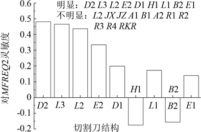
Fig.9 influence of the structure of cutter on frequency spacing between longitudinal vibration frequency and next order vibration frequency(MFREQ2)
In the structure of the cutter, the influence on the uniformity of the output end is R1, B1, R2, and A1. Among them, as the size of B1 and A1 increases, the uniformity increases; as the size of R1 and R2 increases, the uniformity decreases, as shown in Fig. 10.
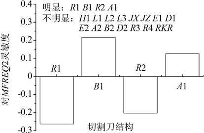
Fig.10 Influence of the structure of cutter on uniformity of cutting edge (SUB_UX)
3 optimization design
According to the sensitivity analysis calculation results, the design variables of the secondary optimization selection are: H1, L1, L2, L3, E1, A1, B1, D1, E2, A2, B2, D2, R1, R3. The state variables are: MFREQ1, MFREQ2, MFREQ3; the upper and lower limits of the constraint state variables are obtained, and the precise resonance frequency and the single longitudinal vibration mode are obtained. Objective function: SUB_UX. Optimization method selection: function approximation method (subproblem approximation method).
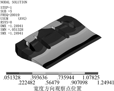
Fig.12 Longitudinal vibration mode shapes of the cutter from optimizing design
Figure 12 is a schematic diagram of the longitudinal vibration mode of the cutting blade after optimization design. The color of the cloud image represents different displacement values, and it can be seen that the displacement of the cutting edge of the cutting blade has high uniformity. Figure 13 shows the displacement amplitude distribution of the cutting edge in the longitudinal vibration mode, and the uniformity of the cutting blade is 0.93.
The longitudinal vibration of the cutter has a resonance frequency of 20019 Hz, an error of 0.01% with the target frequency of 20000 Hz, and a frequency interval of more than 500 Hz, that is, the optimized cutter has a precise resonant frequency and a pure longitudinal vibration mode.

Fig.13 Displacemnt amplitude distribution of the cutting edge
