- All
- Product Name
- Product Keyword
- Product Model
- Product Summary
- Product Description
- Multi Field Search
 English
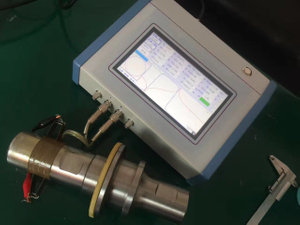
 |

| Frequency precision: | |
|---|---|
| Test precision: | |
| Test speed: | |
| Quantity: | |
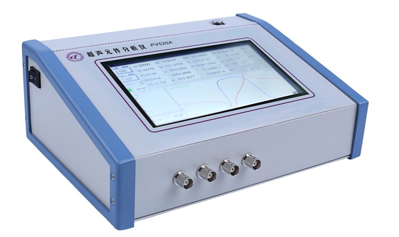
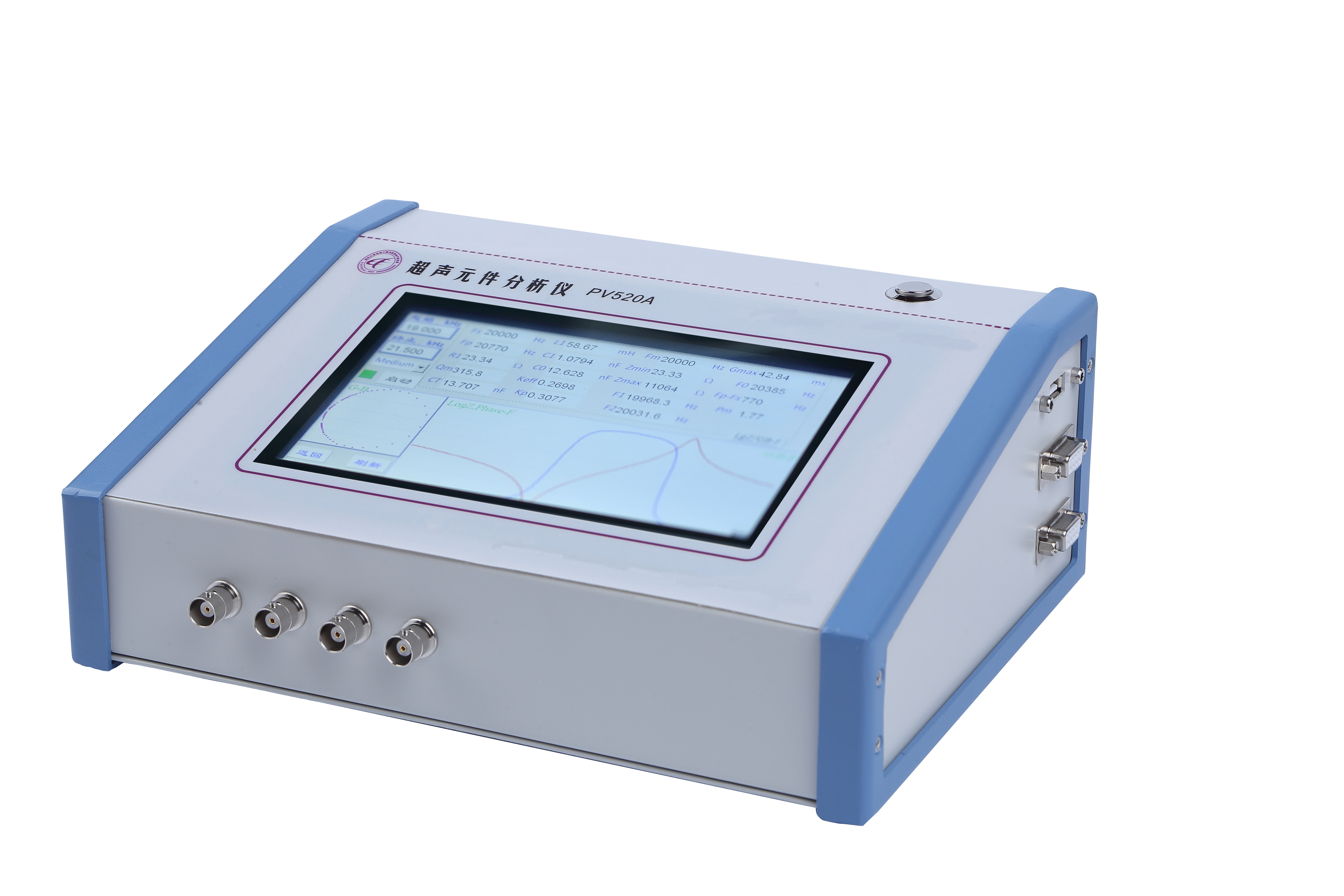
PV520A
Rps-sonic
PV520A
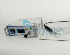
High Frequency Compatible Ultrasonic Impedance Analyzer for Ultrasound Transducers
How to To evaluate the performance of the ultrasonic transducer?
To evaluate the performance of ultrasonic vibration system, it is necessary to analyze from two aspects: parameters and admittance curves:
1) Parameters:
The impedance analyzer can be used to evaluate the performance of various devices such as piezoelectric ceramic sheets, piezoelectric transducers, and entire vibration systems (transducers plus horns, molds). Analysis of ultrasonic device equipment with an impedance analyzer, the most important parameters are as follows:
Fs: The mechanical resonant frequency, ie the operating frequency of the vibration system, should be as close to the expected value as possible in the design and must match the power supply operating point.
For a cleaning machine, the higher the resonant frequency consistency of the vibrator, the better.
For plastic welders or ultrasonic machining, if the horn or mold design is unreasonable, the resonant frequency of the vibrator will deviate from the operating point.
R1: Dynamic resistance, the resistance of the series series of piezoelectric vibrators, the smaller the better under the same support conditions. For cleaning or welding vibrators, it is generally between 5 Ω and 20 Ω. If it is too large, the vibrator or vibration system will have problems, such as circuit mismatch or low conversion efficiency, and short life of the vibrator.
Qm: mechanical quality factor, determined by the conductance curve method, Qm=Fs/(F2-F1), the higher the Qm, the better, because the higher the Qm, the higher the vibrator efficiency; but the Qm must match the power supply, the Qm value is too high The power supply does not match.
For cleaning the vibrator, the higher the Qm value, the better. Generally speaking, the Qm of the cleaning vibrator should be between 500 and 1000. If it is too low, the vibrator efficiency is low. If it is too high, the power supply cannot be matched.
For ultrasonic welding or machining, the Qm value of the vibrator itself is generally around 500~1000, and the whole system is 1500~3000. If it is too low, the vibration efficiency is low, but it can't be too high, because the higher the Qm, the more the working bandwidth Narrow, the power supply is difficult to match, that is, the power supply is difficult to work at the resonant frequency point, and the device cannot work.
CT: Free capacitance, the capacitance value of the piezoelectric device at 1 kHz. This value is consistent with the value measured by the digital capacitance meter. This value subtracts the dynamic capacitor C1 to get the true static capacitance C0, C0 = CT-C1. When using, balance C0 with inductance.
In the circuit design of a washing machine or ultrasonic processing machine, properly balancing C0 can increase the power factor of the power supply. There are two methods for using the inductor balance, parallel tuning and series tuning.
Fp: anti-resonance frequency, the resonant frequency of the parallel branch of the piezoelectric vibrator. At this frequency, the impedance Zmax of the piezoelectric vibrator is the largest. If the anti-resonant impedance Zmax is low, the vibrator has a problem.
2) Graphics
The impedance analyzer provides five kinds of coordinate characteristic diagrams, and the logarithmic characteristic diagram has important significance for the detection of piezoelectric devices. The vibration performance of a piezoelectric vibrator or a vibrating system can be directly judged by a logarithmic graph, which is relatively intuitive and practical.
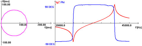
Under normal circumstances, the admittance circle and the conductance curve are as shown in the following figure.
The admittance circle is a single circle, and the logarithmic graph has only a pair of minimum and maximum values:
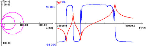
Under abnormal conditions, the admittance circle and the conductance curve are as shown in the figure below. There are multiple parasitic small circles on the admittance chart. The logarithmic graph has many pairs of minimum and maximum values:
Service and shipment
Warranty one year for transducer.
You can contact us for technical inquiry any time.
We supply OEM service for oversea customer, also will keep Confidentiality for our customers.
We supply customized products service for small quantity also.
Shipment by FED-EX /DHL
High Frequency Compatible Ultrasonic Impedance Analyzer for Ultrasound Transducers
How to To evaluate the performance of the ultrasonic transducer?
To evaluate the performance of ultrasonic vibration system, it is necessary to analyze from two aspects: parameters and admittance curves:
1) Parameters:
The impedance analyzer can be used to evaluate the performance of various devices such as piezoelectric ceramic sheets, piezoelectric transducers, and entire vibration systems (transducers plus horns, molds). Analysis of ultrasonic device equipment with an impedance analyzer, the most important parameters are as follows:
Fs: The mechanical resonant frequency, ie the operating frequency of the vibration system, should be as close to the expected value as possible in the design and must match the power supply operating point.
For a cleaning machine, the higher the resonant frequency consistency of the vibrator, the better.
For plastic welders or ultrasonic machining, if the horn or mold design is unreasonable, the resonant frequency of the vibrator will deviate from the operating point.
R1: Dynamic resistance, the resistance of the series series of piezoelectric vibrators, the smaller the better under the same support conditions. For cleaning or welding vibrators, it is generally between 5 Ω and 20 Ω. If it is too large, the vibrator or vibration system will have problems, such as circuit mismatch or low conversion efficiency, and short life of the vibrator.
Qm: mechanical quality factor, determined by the conductance curve method, Qm=Fs/(F2-F1), the higher the Qm, the better, because the higher the Qm, the higher the vibrator efficiency; but the Qm must match the power supply, the Qm value is too high The power supply does not match.
For cleaning the vibrator, the higher the Qm value, the better. Generally speaking, the Qm of the cleaning vibrator should be between 500 and 1000. If it is too low, the vibrator efficiency is low. If it is too high, the power supply cannot be matched.
For ultrasonic welding or machining, the Qm value of the vibrator itself is generally around 500~1000, and the whole system is 1500~3000. If it is too low, the vibration efficiency is low, but it can't be too high, because the higher the Qm, the more the working bandwidth Narrow, the power supply is difficult to match, that is, the power supply is difficult to work at the resonant frequency point, and the device cannot work.
CT: Free capacitance, the capacitance value of the piezoelectric device at 1 kHz. This value is consistent with the value measured by the digital capacitance meter. This value subtracts the dynamic capacitor C1 to get the true static capacitance C0, C0 = CT-C1. When using, balance C0 with inductance.
In the circuit design of a washing machine or ultrasonic processing machine, properly balancing C0 can increase the power factor of the power supply. There are two methods for using the inductor balance, parallel tuning and series tuning.
Fp: anti-resonance frequency, the resonant frequency of the parallel branch of the piezoelectric vibrator. At this frequency, the impedance Zmax of the piezoelectric vibrator is the largest. If the anti-resonant impedance Zmax is low, the vibrator has a problem.
2) Graphics
The impedance analyzer provides five kinds of coordinate characteristic diagrams, and the logarithmic characteristic diagram has important significance for the detection of piezoelectric devices. The vibration performance of a piezoelectric vibrator or a vibrating system can be directly judged by a logarithmic graph, which is relatively intuitive and practical.
Under normal circumstances, the admittance circle and the conductance curve are as shown in the following figure.
The admittance circle is a single circle, and the logarithmic graph has only a pair of minimum and maximum values:
Under abnormal conditions, the admittance circle and the conductance curve are as shown in the figure below. There are multiple parasitic small circles on the admittance chart. The logarithmic graph has many pairs of minimum and maximum values:
Service and shipment
Warranty one year for transducer.
You can contact us for technical inquiry any time.
We supply OEM service for oversea customer, also will keep Confidentiality for our customers.
We supply customized products service for small quantity also.
Shipment by FED-EX /DHL


